Archive Section


Visit to BLS Spiez Signalling Centre and Lötschberg Tunnel Cab Ride
Friday 20th September 2002
© Pictures and text by Tom Chaffin
|
Part I of this article details the rest of the week- |
Note: this page contains thumbnail images. Clicking the thumbnail will open a larger image.
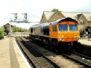
Not for the first time this week, we caught the 08.24 train from Ringgenberg on the SBB Brnig line to Interlaken Ost, followed by the 08.39 ICE to Spiez. We met our guide for the day, Hanspeter Hunkeler of the BLS Lötschbergbahn AG on the platform at Spiez.
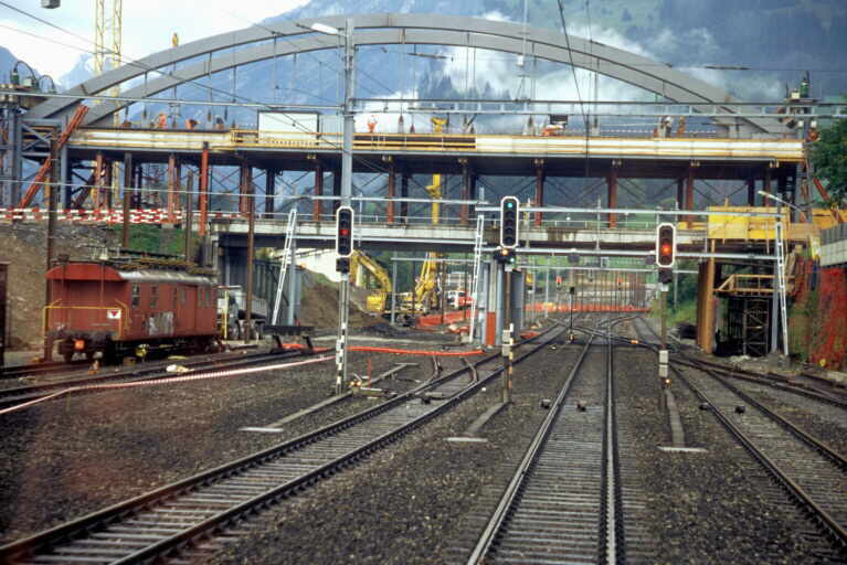
Spiez Signalling Centre:
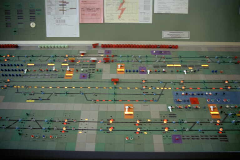
Our first visit of the day was to Spiez Signalling Centre, which is a relatively new installation being completed in the mid 1990's. Spiez controls approximately 30km of route: to Interlaken, as far as Thun on the line towards Bern and as far as Frutigen on the Brig route. The signalling centre is owned and operated by BLS. Despite being recent, all interlocking is by relay-
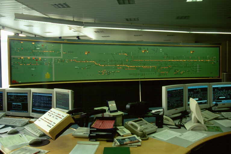
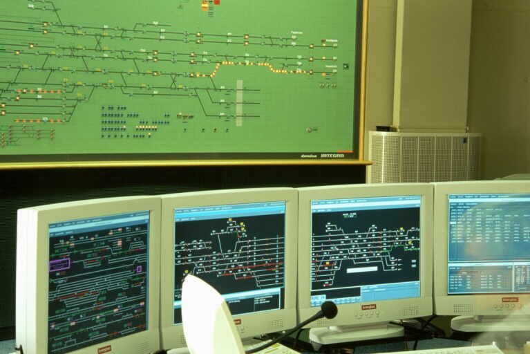
Dominating the operating floor is a tiled mimic panel in pea green and rather familiar in appearance to panels installed in most UK signalling centres. The panel shows the track in the Spiez station area and a couple of kilometres in each direction. Conventional route entry and exit buttons are included on the mimic diagram, but only used in emergency following equipment failure. Routes can also be closed for maintenance possession by pressing buttons on the mimic. Three workstations are located in front of the mimic, each with six monitors -
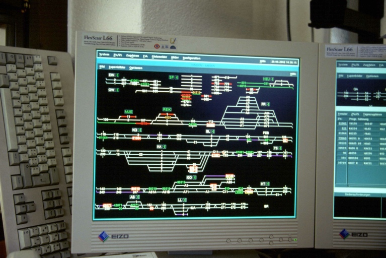
Routes are set by mouse click. Automatic train control and automatic route setting are both employed, which in normal operation automatically set routes after reference to the train reporting number and the timetable -
One screen consists of a telephone concentrator and combines signal telephone and cab-
Of the remaining screens, one is a 'windows' PC system used to display train-
Finally, a small temporary NX (entry/exit) panel is installed on the operating floor to operate the Krattighalde interlocking area, which had been damaged by rock fall.
Spiez to Kandersteg on the Footplate:
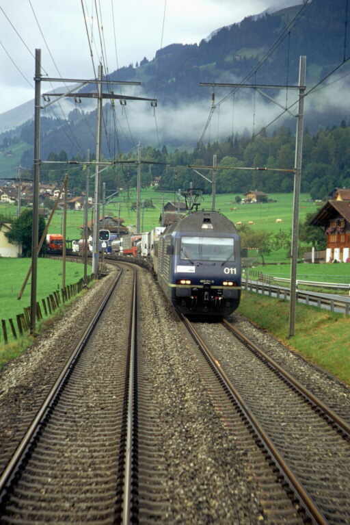
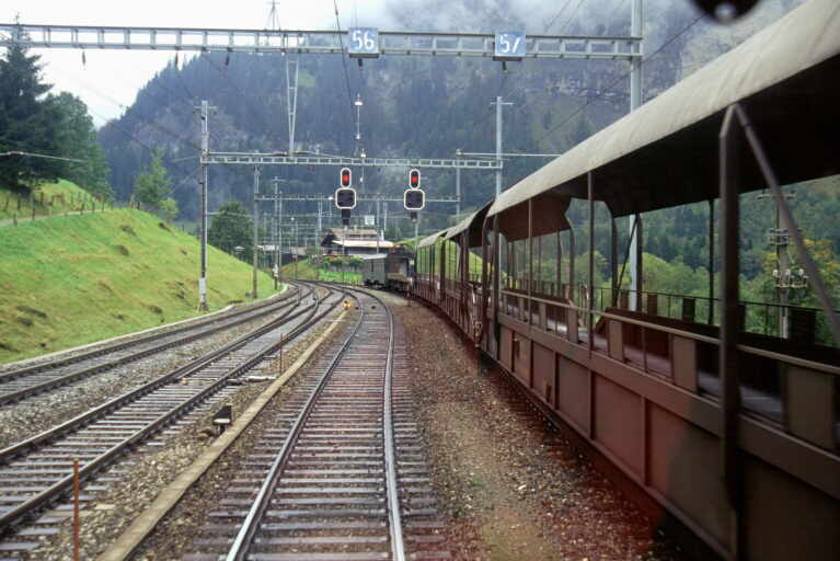
After leaving the signalling centre we were then fortunate to be given the opportunity to travel in the cab of SBB Class Re460 locomotive, 460-
No sooner had we climbed into the cab and got into comfortable positions than the signal in front of us indicated we had the right of way and we rapidly moved off.
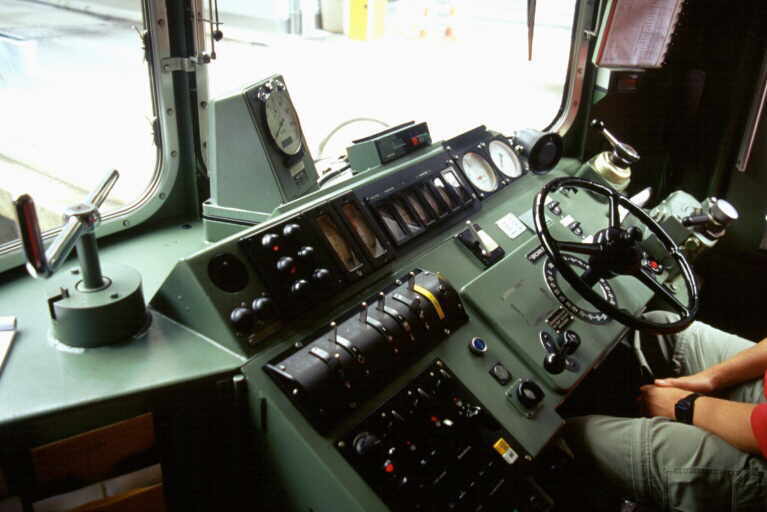
Immediately obvious was the excellent driver visibility form the large single-
Click images for an enlargement
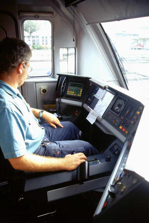
Power controller on driver's right, configured as follows: central position -
Immediately in front of the driver is a large analogue speedometer, with a red pointer indicator at the adjustable speed-
Click image to enlarge
A vigilance system is fitted which, if the controls have not been moved for a period of time, give a 'beep-
Like in the UK, the left-
I was standing up in the rear of the cab behind the driver and it suddenly dawned on me that it was the first time I had ever stood on a locomotive footplate without having to hold onto anything; I was standing without support due to a combination of superb Swiss P.Way and excellent locomotive ride. Noise levels were also low, the main noise being some traction motor whine from directly below.
Click images for an enlargement
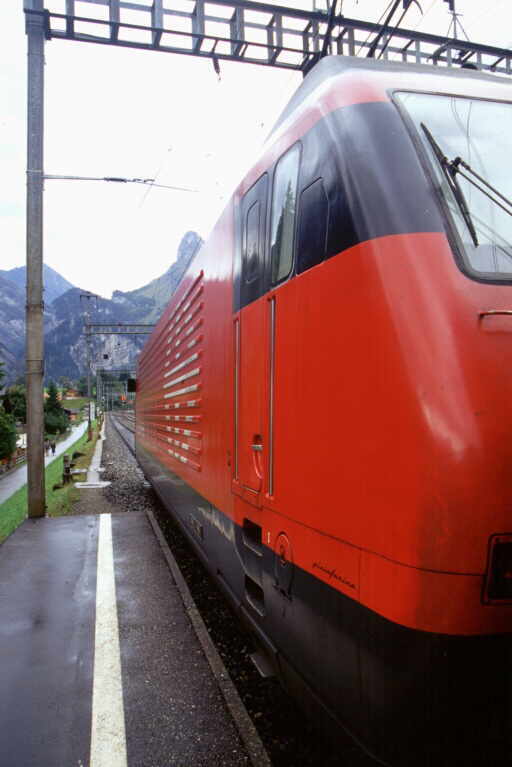
Approaching the first station, Frutigen, the driver reduced speed using the combined power / electric brake controller, including use of the 'maximum' electric brake position and as speed fell, simultaneously used the train air-
Departing, it was noticeable that on 50% power, acceleration was reduced and with the heavy load and gradients, maximum line speed was not quite achieved. For some of the journey to our next station we were routed 'wrong road' on the right hand track due to engineering work on the other line. Like most Swiss lines, both lines were bi-
Kandersteg Lötschberg Tunnel Introduction:
The 14.6km Lötschberg Tunnel provides a route through the Alps massif from Switzerland and Northern Europe through to Italy. Work commenced on building the tunnel in 1906 and was complete by 1911. Initially the tunnel was used for just rail traffic, but in 1950 BLS conveyed 225 road vehicles through the Lötschberg Tunnel on special rail transporter wagons. Car terminals were set-
At the end of 1993 BLS was commissioned by the Confederation to provide a piggyback corridor for trucks with a maximum width of 2.5m and a height of 4m on the line through the Lötschberg Tunnel, pending the commissioning of the base tunnel. Construction work to modify the tunnel began in January 1994. Opening was delayed due to geological problems on the southern side of the Simplon, but operations finally began on 11 June 2001. Special truck transporters with small wheels are used to keep within the loading gauge.
On 27 September 1992 the Swiss people voted with an overwhelming majority in favour of the NEAT Project (NEAT = Neue Alpentransversale, also known as the AlpTransit), giving approval for the construction of two transversal routes through the Alps, one at the Gotthard, the other at the Lötschberg. The original AlpTransit Lötschberg Project provided a 41 km base tunnel, with two tubes between Frutigen and the Rhne valley. However, for financial reasons, the project's dimensions had to be revised: the new tunnel length is now 34.6 km, and one of the two tubes is to be built initially only as a shell. Providing the project can be completed on schedule, trains will start running through the Lötschberg Base Tunnel in 2007.Kandersteg
Lötschberg Tunnel Control
Just off one of the station platforms at Kandersteg station is the control room for train movements through the tunnel and we were invited to view these by BLS Ltschbergbahn. At the back of the relatively small control room is the electrical control panel for the tunnel. In front of this is a large NX signalling panel for the tunnel, plus two workstations. Each workstation has two monitors capable of displaying a track/signalling display plus other screens of information, such as on the booked timetable, as required by the signalman. A Neumann telephone and radio concentrator is also installed on each workstation, as well as PA control and hot axle box detection indicators. Automatic route setting is used by the workstations, reducing operator workload. The NX panel, which like in Spiez can takeover following equipment failure, mimics the area controlled by the workstations, albeit without automatic route setting. The way set routes and trains are displaced on the workstation would not be unfamiliar to those used to British signalling systems
Click images for an enlargement
Through the Lötschberg Tunnel on the footplate:
We were then taken across the car terminal marshalling area and into the car shuttle train crew mess room. This was the best railway mess room I had ever come across, consisting of an almost new self-
In the holiday season car shuttles depart every 15 minutes on Saturdays and Sundays and every twenty minutes on other days between about seven in the morning and seven in the evening. A thirty-
Each shuttle consists of a driving trailer vehicle at the Goppenstein end; a number of open, but roofed, transporter wagons and finally a Class Re4/4 locomotive at the southern end. The driving trailers are either EMU conversions or have been purpose-
We were to ride on train number 30121, booked to take 18 minutes for the journey and propelled by Re4/4 locomotive 179 "Bern", which was built in 1972 and fitted with Brown Boveri electrical equipment. As we were travelling towards Goppenstein we had to first walk down the train to the driving trailer through the empty car transporter wagons, which was an experience in itself.
On the Re 4/4 locomotives the electric brake works in one of two modes: regenerative, where current is returned to the overhead traction supply when it is 'receptive', i.e. another train is in the area drawing power, or rheostatic, where the energy is dissipated as heat through resistance banks on the ocomotive when the overhead is not receptive.
The driving trailer was one of the purpose made coaches, but the cab was similar to EMUs of the same generation. Dominating the driver's desk is a central wheel, which is moved clockwise to apply power. A lever next to the wheel initialises the electric (locomotive) brake, which is progressively applied by moving the wheel anti-
Click images for an enlargement l
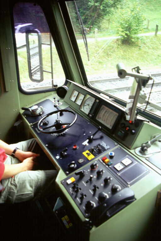
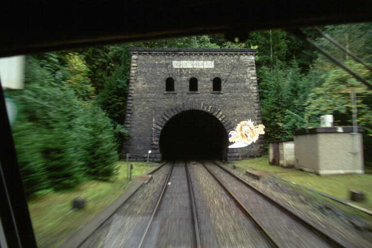
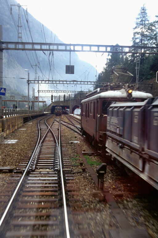
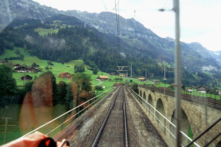
Unfortunately I was unable to take many notes whilst riding through the tunnel, as it was not possible to write in the dark! However, after around quarter of an hour in the tunnel, we emerged into the open and almost immediately entered the Goppenstein terminal, gently kissing the buffer stops as we came to a stand -
We then walked around the terminal approach road, part of which was on a spectacular viaduct over a valley and rejoined the train at the locomotive end for the trip back.
The locomotive cab was essentially very similar to the driving trailer, but with more switches and a prominent handbrake 'wheel'. The main reservoir and train brake gauges were combined into two dials on the same instrument on the locomotive. It was noticeable that the locomotive was rougher riding than the driving trailer, though still quite respectable. As trains passed each other in the tunnel, the drivers greeted each other by momentarily switching on their cab lights. As I was rather enjoying the experience, all too soon we arrived back at Kandersteg and after saying farewell to our driver and having a very good value lunch in the station restaurant with our host, Hanspeter Hunkeler, we then had the rest of the afternoon free.
I chose to have a quick wonder around the picturesque village of Kandersteg, noticing that in this almost crime-
Related pages:
|
Part I of this article details the rest of the week- |
|
|
Lecture on BLS Lötschbergbahn AG by the Institution's vice president Willi Frauenfelder. |
|